This is Arduino
By Maarten H. Lamers
Media Technology MSc program
Leiden University, Institute of Advanced Computer Science (LIACS)
This lecture is part of the course Hardware & Physical Computing. It introduces Arduino i/o boards through simple examples that demonstrate how to connect and program the board. It should give you enough knowledge to decide if you can use the Arduino i/o board in interactive objects and artworks. Basic programming skills are assumed, but you need not be an excellent programmer to understand the examples. Programming examples are in the Arduino and Processing languages. No knowledge of electronics is assumed.
Video lectures
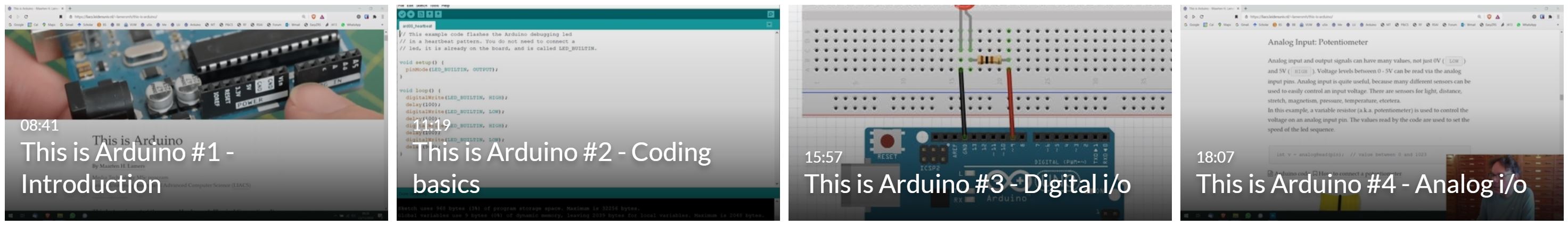
Most of the material below is explained in a series of twelve short video lectures, each between 5 and 18 minutes long. It is best to watch the video lectures one-by-one and use this webpage to read along, download my example code, and try each tiny Arduino project yourself.
About Arduino
Arduino boards make it possible to digitally interface with the real physical world. You can program an Arduino board to drive motors, measure humidity, open valves, read the state of switches, control leds, set off fireworks, measure acceleration, vibrate, and much more. The boards can control all kinds of sensors and actuators. Sensors allow the board to acquire information from the surrounding environment (temperature sensors, light sensors, distance sensors, etc). Actuators are devices that allow the board to create changes in the physical world (lights, motors, heating devices, etc). It can also interact easily with other devices and computers, such as your PC/Mac, GPS receivers, barcode readers. Arduino boards are popular, because they are cheap and have many connection capabilities. Also, they can be easily programmed in a variant of the Processing language, with a similar programming environment.
Arduino is an open-source hardware project, initiated by Massimo Banzi and friends, and documented on www.arduino.cc. Its design is based on Processing, the open source programming language and environment, and Wiring i/o boards by Hernando Barragán. Different types of Arduino boards exist, ranging in size and power. For example, LillyPad Arduino's were designed to be sewn into clothing and textiles, and Arduino Nano is quite small. If you are new to this, get the Arduino UNO.
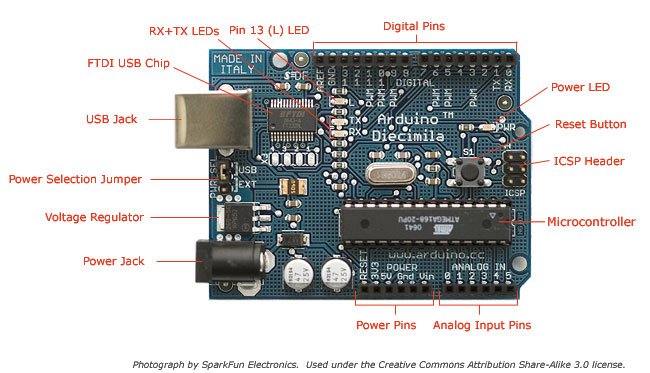
Basic versions of Arduino boards, the UNO and older Diecimila, have:
-
14 digital i/o pins, of which 6 can be analog output (PWM) pins
6 analog input pins
multiple serial ports (at the expense of digital i/o pins)
2 external interrupt pins
1KB EEPROM, easily accessible from code (512 bytes for Diecimila)
a very useful debugging LED
USB-to-serial connection
power from external supply (9V center-positive, 2.1mm plug) or USB
How to Upload Code to the Arduino
These are the steps to use the i/o board:
-
Write a program in the Arduino programming environment,
Connect the i/o board to your computer via USB,
In menu 'Tools' / 'Board' select which type of Arduino is connected,
In menu 'Tools' / 'Port', select where the Arduino is connected,
Click the 'upload' button to send your program to the i/o board,
After uploading, the code runs automatically!
If power comes from an external power supply (like a 9V battery), you can disconnect the USB cable and the board keeps running your program.
Even after all power was switched off, the i/o board retains your program in memory. When you reconnect the power, it starts running automatically.
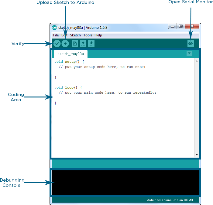
(Image: screenshot of the Arduino IDE; image source)
Code Basics
All Arduino code is written around two important functions, setup() and loop(). When you place code inside these functions, it executes as follows:
setup() is executed once, on Arduino power-up/reset,
after this, loop() is executed repeatedly forever.
n with value 28 and then infinitely increments it, looping n over values 0 ... 255.
int n;

void setup() {
  n = 28;
}

void loop() {
  n++;
  n = n % 256;
}
Hello Arduino!
This is the "Hello world!" example of Arduino, and the first thing you should try. It flashes the board's built-in debugging led in a heartbeat pattern. With this code, you can quickly test if the board functions and can be programmed, without any additional hardware.
pinMode(LED_BUILTIN, OUTPUT);
digitalWrite(LED_BUILTIN, HIGH);
Digital Output: Leds
This example connects several leds to the board, and flashes them in sequence. The leds are connected to digital i/o pins 0-7. When in OUTPUT mode, these digital pins can supply either 0V (LOW) or 5V (HIGH).
pinMode(pin, OUTPUT);
digitalWrite(pin, LOW);
digitalWrite(pin, HIGH);
Arduino code, How to connect a led
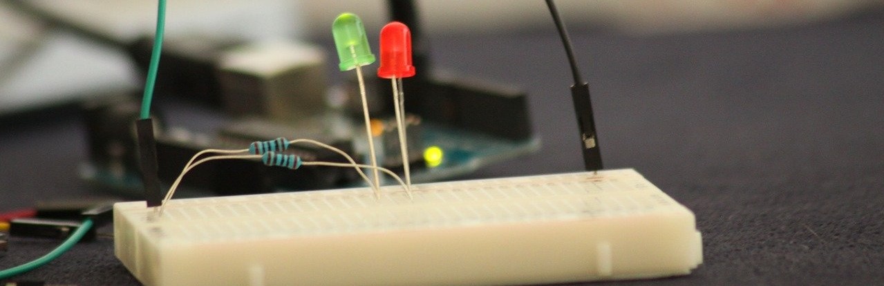
(Image: leds on a breadboard; image source)
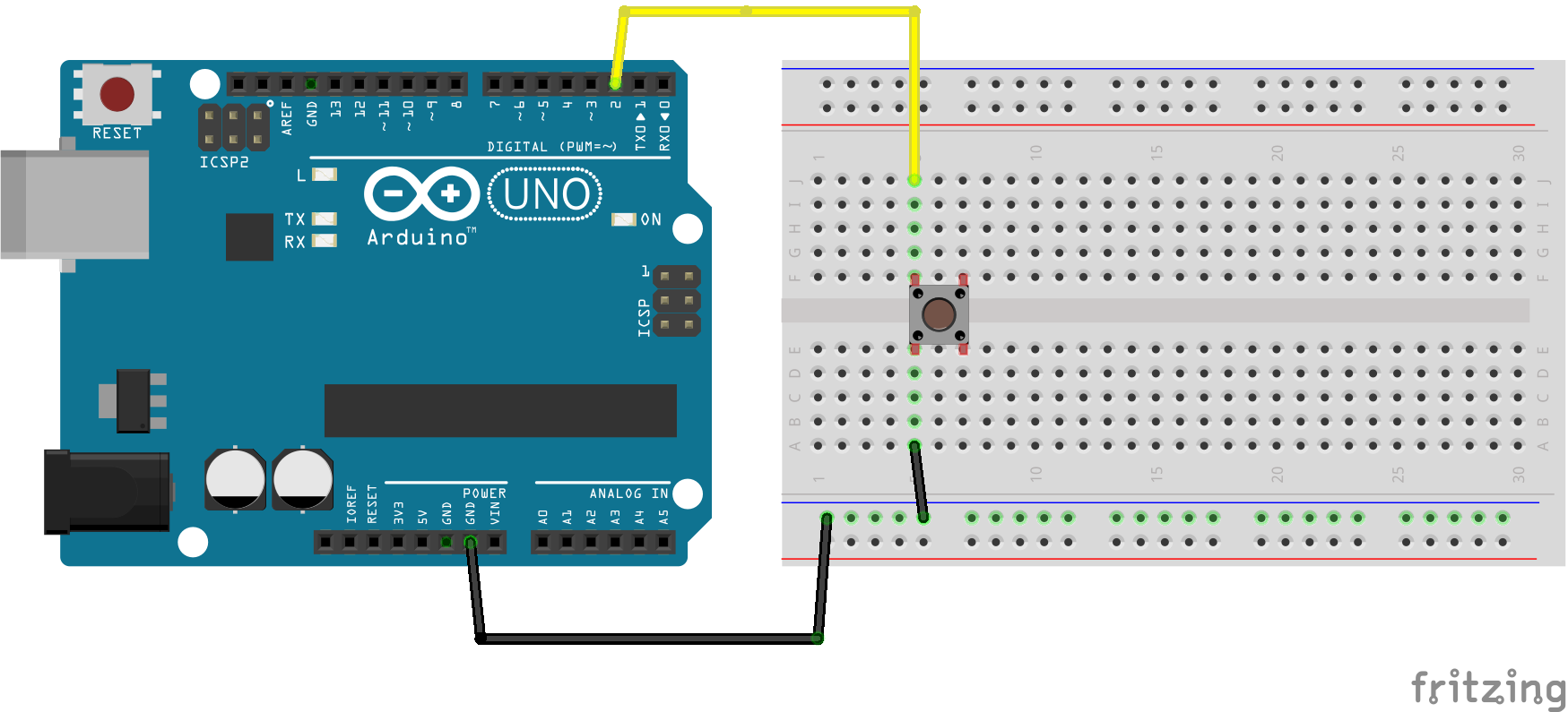
Digital Input: Switch
A digital input signal can be either 0V (LOW) or 5V (HIGH). It can be read via a digital i/o pin, if that pin is set to INPUT mode. To generate digital input signals you must make or break an electrical circuit, such as with a button or switch.
This example uses a pushbutton to control the direction of the led-sequence: pressing it reverses the direction.
pinMode(s, INPUT);
if (digitalRead(s) == HIGH) {
  p--;
} else {
  p++;
}
Arduino code, How to connect a button
Digital Input: INPUT_PULLUP
In the previous example, the button is connected via an external resistor, that functions as a pull-down resistor: it "pulls down" the input pin to 0V (LOW) when the button is released. Pressing the button connects it to 5V (HIGH). Most Arduino boards have internal pull-up resistors that you can use instead of using an external resistor. The state of the input pin is then reversed: LOW when pressed (closing the contact), HIGH when released.
This example does the same as the previous, but needs no external resistor to connect the pushbutton.
pinMode(s, INPUT_PULLUP);Arduino code, How to connect a button with no external resistor
Analog Input: Potentiometer
Analog input and output signals can have many values, not just 0V (LOW) and 5V (HIGH). Voltage levels between 0 - 5V can be read via the analog input pins. Analog input is quite useful, because many different sensors can be used to easily control an input voltage. There are sensors for light, distance, stretch, magnetism, pressure, temperature, etcetera.
In this example, a variable resistor (a.k.a. potentiometer) is used to control the voltage on an analog input pin. The values read by the code are used to set the speed of the led sequence.
int v = analogRead(pin); // value between 0 and 1023Arduino code, How to connect a potentiometer
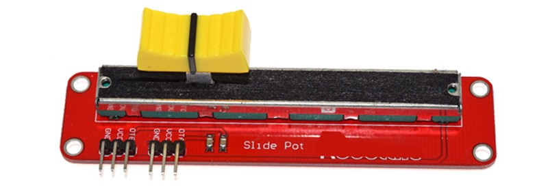
(Image: sliders on a mixing desk are also potentiometers.)
Analog Input: Photoresistor
A photoresistor changes its electrical resistance, depending on how much light it detects. By connecting it to an analog input pin, we make the detected level of ambient light determine the number of leds that light up.
int v = analogRead(pin); // value between 0 and 1023Arduino code, How to connect a photoresistor
Analog Output: Fading Led
Analog output pins can generate voltage levels between 0 - 5V, using a method called Pulse Width Modulation. PWM is basically a way of faking different voltages by very quickly alternating between 0V and 5V: the longer the 5V spikes take, the higher the output voltage appears.
This example makes a led connected to an analog output pin fade in and out, by changing the pin's voltage between 0 - 5V.
analogWrite(a, v); // set analog out pin a to value vLCD Display
Most cheap character-based LCD displays contain the same controller chip (the HD44780, if you must know). Arduino contains a standard library to communicate with this controller chip in a very simple way. This example prints text on an LCD display, and then scrolls it.
LiquidCrystal myLCD(6,7,0,1,2,3);
myLCD.clear();
myLCD.setCursor(4, 1);
myLCD.print("Maarten");
myLCD.scrollDisplayRight();
Arduino code, How to connect an LCD display
If no text appears, despite all your connections and code being correct, then play with the contrast voltage on LCD pin 3 (use a potentiometer). On some LCD displays, this is vital for making the characters visible.
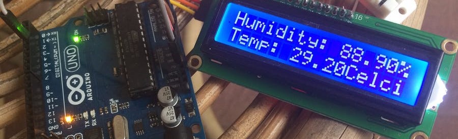
(Image: standard 16x2-character LCD unit. Other sizes and colors exist.)
Serial Communication
The i/o board can communicate with other devices via the serial communication protocol. By emulating serial communication over USB, it communicates with your PC. In this way the i/o board and your computer can interact.
This example code demonstrates outgoing serial communication. Values read from a potentiometer are sent out via the Serial object, separated by newline characters.
Serial.begin(9600);
Serial.println(v);Serial Monitor. The Arduino development environment on your PC includes a "serial monitor" (under "Tools"). It allows you to see what the Arduino sends onto the serial line, which is very useful! You may also want to try Arduino's "serial plotter" (under "Tools"). In either case, make sure that the baud rate selected in the monitor or plotter is set to the same speed in your Arduino code.
Serial Communication, bi-directional
Serial communication can act in two directions simultaneously. This example lets a Processing program on the PC react to data received from the i/o board, and vice versa. By controlling a potentiometer on the i/o board, the color of an object in a Processing application is changed. Meanwhile, mouse positions are sent from the Processing application to the i/o board, and make leds light up.
The computer application can be written in any language that supports serial communication, such as Max/MSP, C, C#, Basic, Python, Pure Data, any language really.
Serial.begin(9600);
Serial.write(v);
if (Serial.available() > 0) {
    int p = Serial.read();
}Two points of attention:
-
The standard serial line (the one called
Serial and used in the above example) uses digital pins 0 and 1. As a result, you should not use these pins for something else while using Serial.
Arduino's "Serial Monitor" also lets you send characters from your PC to the Arduino. Try it with this example's Arduino code.
Firmata
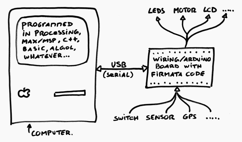
Many projects use the Arduino not as a standalone processor, but as an intermediate device via which to connect sensors, leds, motors, etcetera to a personal computer. In this setup, the board and PC stay connected and communicate via the serial port. An application running on the PC can interact with devices connected to the Arduino board.
To make this setup easier for you, Hans-Christoph Steiner initiated Firmata. If you run Firmata code on a Arduino, then the board interacts with applications written in Processing, Max/MSP, etc, by including the appropriate library. This way, you don't need to write the any Arduino code at all!
In this example, we upload the SimpleDigitalFirmata program (it is supplied with Arduino under menu File > Examples > Firmata) to the board, and interact with it via Processing code. The Processing code makes eight LEDs light up in sequence, just like in the above example "Digital Output: Leds". However, now the LEDs are controlled by the PC, and no Arduino programming is required. Sweet!
my_arduino = new Arduino(this, "COM3", 57600);
my_arduino.pinMode(0, Arduino.OUTPUT);
my_arduino.digitalWrite(0, Arduino.HIGH);
In the next example, we upload the StandardFirmata program (it is supplied with Arduino) to the board, and interact with it via Processing code. This way, we can do exactly the same as the above example ("Serial Communication"), without the need to write any Arduino code.
my_arduino = new Arduino(this, "COM3", 57600);
v = my_arduino.analogRead(0);Analog Accelerometer
An accelerometer measures G-forces along 2 or 3 axes, caused by movement or by gravity. By measuring G-forces caused by gravity, you can know the vertical orientation of the sensor or use it as a tilt-sensor. Analog accelerometers are very easy to use, but difficult to find.
This Processing code visualizes 2-axes acceleration measurements as a vector. The Arduino runs SimpleAnalogFirmata code (no Arduino programming required).
Processing code, How to connect an analog accelerometer
Using a digital accelerometer is slightly more tricky. It requires using I2C communication, which is explained next.
I2C
Many digital sensors and actuators communicate with the Arduino board via the "I2C" bus. This allows you to get much information to/from a device while using only two special pins. On the Arduino UNO, these are analog input pins 4 (SCA) and 5 (SCL).
Every digital I2C device has an address, at which it communicates. For example, my digital accelerometer has address 104. Arduino's Wire library enables you to communicate via I2C with this address. The following example illustrates how to read data from a digital accelerometer using I2C.
Digital Accelerometer/Gyroscope
My digital accelerometer/gyroscope is a very standard MPU-6050 (mounted on a GY-521 board, priced at roughly $5). It communicates via I2C at address 104 (0x68 hexadecimal). Unfortunately, the I2CFirmata code is documented nowhere, so we cannot use Firmata code. Therefore, this example uses Arduino's Wire library to send acceleration, temperature and gyroscope measurements to the PC. A program written in Processing visualizes these values in 3D.
Wire.requestFrom(0x68, 14, true);
v = Wire.read();
Arduino code, Processing code, How to connect an I2C device
Servo Motor
A servo motor is an electrical motor that comes with internal electronics. It can be set into specific positions and can be quite strong. Arduino comes with a library to control standard servo motors and set their positions between 0 and 180 degrees (actually, my own servo appears to go only to 176 degrees). When you send it a position, it will 'slowly' move until it reaches that position.
This example repeatedly moves a servo motor to specified positions.
myServo.attach(9);
myServo.write(90);
Arduino code, How to connect a servo motor
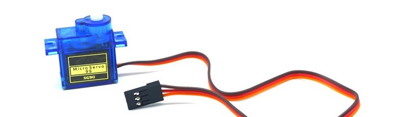
(Image: the standard SG90 servo is cheap and useful.)
External Interrupts
Interrupts are actions that are taken automatically when a specific event happens. These actions literally interrupt the running program. After the interrupt is over, program execution continues where it left off. External interrupts are triggered by changes in a digital input signal. They can be very useful if you want your code to react fast to external events, while keeping your code simple.
In this example we connect a pushbutton to digital i/o pin 2. In code, we then attach a routine to the external interrupt: when the button is pressed, the value of the pin falls (from HIGH to LOW), and the routine is automatically called. Arduino UNO supports two external interrupts, on digital pins 2 and 3.
attachInterrupt(digitalPinToInterrupt(2), myRoutine, FALLING);Using interrupts can be tricky. Two particular points of attention are:
-
While an interrupt routine is running, all other interrupts are blocked. As a result, timers will not work in interrupt routines and other functionality may not work as expected. Therefore, always keep your interrupt routines short and simple.
When you press a physical button, it 'bounces', generating a short and very fast sequence of alternating
HIGH and LOW states. As a result, multiple external interrupts may be generated by one press of a button. Be aware of this.
EEPROM
EEPROM (electrically erasable programmable read-only memory) is memory that retains its content when power is disconnected. This is actually where your program code is also stored on the i/o board.
It is possible for your application to store values in the EEPROM and read them out later, much later, even after power was disconnected. When you upload new code into your i/o board, the values in this particular EEPROM section are not changed. This is very useful if you want your Arduino application to remember its data or configuration for later use. Arduino typically has 512-1024 bytes of EEPROM memory available to store values in.
b = EEPROM.read(28);
EEPROM.update(28, b);
Update versus write. Writing data to EEPROM costs relatively much time (roughly 3.3ms per byte). Moreover, EEPROM has a limited lifespan of 100.000 write actions. Therefore it is better to use EEPROM.update() instead of EPROM.write(), since it only writes a byte if its value changes.
ESP8266 WiFi Chip
The Arduino programming language and interface also work for other boards than Arduino ones. For example, it can also be used for boards based on the ESP8266 chip, which combines a microcontroller, WiFi chip, and TCP/IP stack. This enables such boards to communicate via WiFi and even run a small webserver, which is a first step in making your own Internet-of-Things products.
Many boards exist that use the ESP8266 chip, I use the NodeMCU board. To select it from the "Tools:Board" menu of Arduino, you may need to install a package first. There are plenty sites that tell you how to do this. I used instructables.com. The examples provided here should also work on other ESP8266 based boards.
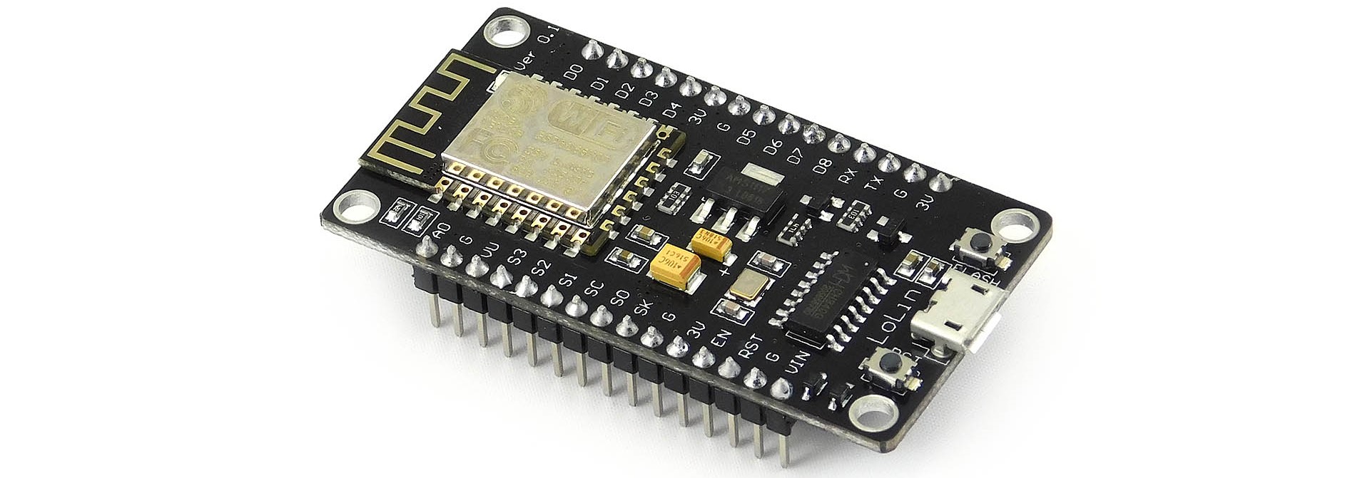
(Image: a NodeMCU board, based on the ESP8266 chip, can be programmed as an Arduino.)
Web-server. The below Arduino code sets up the board as a small webserver (HTTP server) that offers control over the built-in LED via a web-browser, from your phone for example. Naturally, you can connect other devices to the board to make more interesting applications than this. Upload the code to the board, then set your Serial Monitor to 115200 baud. Connect your phone to the same WiFi and open the webpage address shown in the Serial Monitor.
Web-client. The next code example makes the board into a web-client (HTTP client) that uploads data to a website. Every 20 seconds it measures the status of its WiFi connection, and uploads it to my Thingspeak.com channel. This should give you a general idea how to create an IoT sensor.
Where to buy Arduino and components
Nothing is more killing for a project than to have a great idea, and then wait 6 weeks for the parts to arrive from China. Students frequently ask me where I buy my parts. Well, here:
-
First, I always check martktplaats.nl for parts that I need. Often, someone sells it and you can either pick it up or get it sent the next day.
If I need advice or want to get components fast from a real (physical) shop, I go to MUCO Electronics (Burgemeester Roellstraat 32) in Amsterdam. They are friendly and have many components and Arduino boards in stock at good prices. Also, they have very decent opening hours.
I have good experiences with buying parts and Arduino boards from tinytronics.nl.

Need a fun project idea? The Vulcano-detector
Several years ago, I made a "vulcano-detector" for my son (then 5 years old). Inside an old shoebox I mounted an Arduino, powered from a USB powerbank. It drove a small servo-motor and a single red LED, both taped to the outside of the box. The servo-motor had a cardboard arrow attached, that would point in a random direction every 20 seconds or so "indicating where the nearest vulcano is". Roughly every two minutes, the red LED would blink alarmingly for 10 seconds, indicating that "a volcanic eruption was about to occur". Then I just sat back and watched my son and his friends run excitedly around the neighborhood for two hours, warning strangers about the imminent danger of lava flooding our streets.

Alternatives to Using Arduino
Often I see students use Arduino when another solution to their problem would have been easier, more stable, cheaper, or less work. But what are these alternative solutions? I have created a separate page that lists some alternatives to using Arduino, and describes their pro's and cons. You may want to check it out before investing time, money and effort in Arduino when a better alternative exists.
Acknowledgements
-
A particular warm thank you to Hernando Barragán for sharing his excellent Wiring connection examples.
Thanks to anyone who contributed to the Wiring and Arduino projects!
Links
-
Arduino, Wiring, and Processing projects.
My page about Alternatives to Using Arduino.
Article in Wired Magazine 16(11), 2008, about the history of open source Arduino.
My own library for decoding of GPS data on the Wiring i/o board.